by Richard Freudenberger, Living Web Farms Energy & Resource Coordinator
Earlier this year at Living Web Farms we completed a propagating facility for Black Soldier Fly (Hermetia illucens) larvae at our Grandview Farm. The Black Soldier Fly, or BSF, has a similar appearance to a mud dauber wasp but is not a nuisance to humans, nor is it a vector for disease.
A soldier fly larval colony is a very efficient composter of manures and organic materials, and the larvae themselves a source of protein-rich feed for poultry and fish. Residues from the colony can be applied as organic fertilizer, so the BSF production process is a quite sustainable and worthwhile undertaking for an agricultural operation.
The mating cycle of the Black Soldier Fly is active in temperatures between 24 and 37 degrees C (75 to 99 degrees F). In cooler environments they will simply go dormant but excessive heat can be detrimental or fatal, so in cultivation some type of climate control is necessary.
Our production facility is a modified 1,173 cubic-foot shipping container. The 20-foot cube was chosen because of availability, integrity of its unit construction, and long-term protection from the elements. These steel-clad containers are not at all designed for thermal efficiency, so we had to make modifications to amend that, keeping in mind the importance of passive energy design and long-term resiliency.
To ready the container for a suitable habitat, we insulated the interior walls and ceiling with 4 inches of extruded polystyrene (XPS) panel, which is not affected by moisture as expanded polystyrene is. The resulting insulation value of R-20 is a suitable balance between energy loss and available space inside, since the panels reduced interior volume to 880 cubic feet, or 75 percent of the cube’s original size.
A soil-covered living roof planted with a medicinal herb and a cover crop helps dissipate heat through evaporation, and water curtains on the southern and western exposures will activate should temperatures ever reach critical levels. Within time, growth from the jiaogulan herb and any subsequent plantings will overhang the walls exposed to direct sun, shielding the container’s steel skin in high-heat season.
But the main feature of passive climate control in the structure, and the subject of this blog, is a system of earth-coupled cooling tubes used in conjunction with a solar chimney that works to moderate airflow through the chamber to bring a temperate environment within.
Such cooling tubes, sometimes referred to as earth-tube heat exchangers, are lengths of ventilation pipe buried in the soil at depths between 5 and more than 12 feet. The depth, overall length of pipe, and number of pipes used are dependent on the structure, soil composition, and topography at the site.
In simplest terms, think of a box that has a long tube going into one end of it, and a short tube extending from its top. To get airflow moving through the box, you would either have to blow air into the long tube or draw air from the short tube. Both ends must remain open or flow cannot occur. If one end is blocked, air movement is stopped no matter how much you try to blow or draw through the tubes.
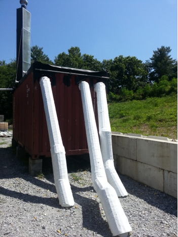
In our case, the long tubes are three 192-foot sections of 6-inch thinwall PVC pipe buried in parallel trenches at a depth of 6 feet. The pipes’ inlet points extend from the ground about waist-high at a 45-degree angle and are covered by a shading screen to avoid direct sunlight (and heat) exposure. The three exit points are near the top of the container some 60 yards distant, sealed tightly against the container walls.
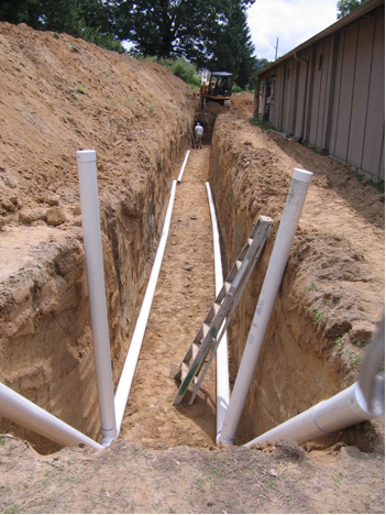
Two of the three 192-foot earth-coupled pipe runs prior to being backfilled in the soil. Spacing is maintained between each tube to give the soil a thermal bank to draw from while subsurface temperatures recharge. Photo by R. Freudenberger
At the opposite end of the container a 10-inch diameter galvanized pipe extends vertically 14 feet from a sealed junction box welded into the structure’s roof. Surrounding the pipe is a rectangular metal frame lined with 2 inches of foil-faced polyisocyanurate insulation and covered with Sun-Lite HP fiberglass glazing.
This vertical pipe is a solar chimney which initiates airflow through the system. After about 10 am, when sunlight strikes the chimney’s south-oriented glazing panel, enough heat is absorbed by the black-painted galvanized pipe to induce a vertical draft. As the heated air rises, it has to draw from the air supply within the container, and as that supply moves out and upward, it is replaced by air from the buried tubes which is cooler, and denser, than the air it replaces.

A solar chimney induces natural airflow through the system, functioning on the principle that hot air rises. Photo by R. Freudenberger
This natural, passive flow continues as long as the sun shines, and naturally intensifies at the hottest part of the midday when solar radiation is greatest and when the greatest inside temperature reduction is needed. To assist flow during cloudy spells, we’ve installed a wind-driven ventilation turbine at the top of the chimney that allows greater free-flow than a simple cap and induces flow in wind velocities of less than 4 mph.
As an active backup, I felt it was necessary to include forced-air ventilation within the earth tubes and had to specify a fan that would not restrict the airflow of the passive system and would use a minimal amount of energy when operating. I located a 6-3/4-inch 38-watt metal axial fan with about 50 percent open flow that moved 198 cubic feet per minute at 110 volts AC. Three of these fans wired through an in-line thermostat pull cooled air through the buried tubes when the interior temperature reaches 30 degrees C (86 degrees F). Their amperage draw is low enough that a modest investment in a small inverter and solar panel would get the system off-grid.
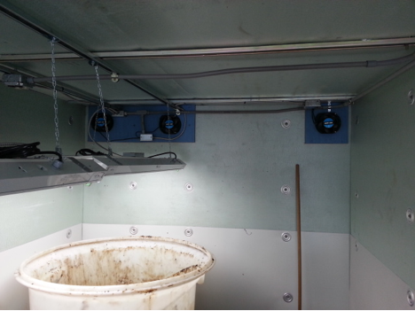
A fan-driven backup system is in place, which only activates when interior temperatures rise above 86 degrees F. The axial fans allow ample free flow when not powered. Photo by R. Freudenberger
The concept of cooling tubes is easy to comprehend but not so simple to put into practice. The notion that the soil below two or three feet depth maintains a 50 degree F temperature year-round and worldwide is both wrong and stubbornly persistent. The actual equilibrium depth is likely closer to 20 or 30 feet, and the site latitude has a significant impact on mean temperatures, along with soil composition and vegetative growth on the surface.
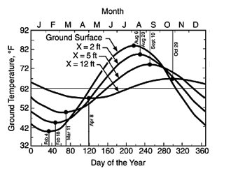
Seasonal soil temperature change related to depth below ground surface for moist soil. Image courtesy Virginia Tech
From a practical standpoint, designing a functional earth-coupled ventilation system is a compromise of several factors, not the least of which are the cost of excavation and materials, the flexibility of the site plan, the difference in temperature between ambient outside air and the target goal, and seasonal requirements.
In our situation, we had a specific footprint for the cooling tube field, dictated by an earthen bank along the southern side and our biochar facility at the north, which left about 15 feet of width and a 60-yard open run that is also a vehicle access. Because we were installing a retaining wall at the bank, excavation equipment was available, so some cost was defrayed.
While heat capacity of soil is significant, its conductivity is not. The tubing material is not so critical other than its structural qualities (the PVC we used has a crush strength of 3,000 psi) and its ability to conduct thermal energy. When considering metal and concrete, cost goes up, as it also does when larger diameter pipes are used.
We used 6-inch diameter thinwall drain pipe because it’s very common and its surface area over the nearly 600 feet of run provided enough residency time for the air to absorb coolth on the pass through. Larger pipe (20 inches in some cases) is more common in commercial projects, but expenses increase drastically with size.
Another way to increase surface contact is to increase pipe length but at some point the resistance to airflow becomes a problem and forced-fan flow is needed, a situation which we view as backup only. Another option is to add more pipe runs and keep them shorter, but our field was too narrow to allow the 5-foot spacing between pipes needed to maintain the thermal storage bank that the tubes draw from.
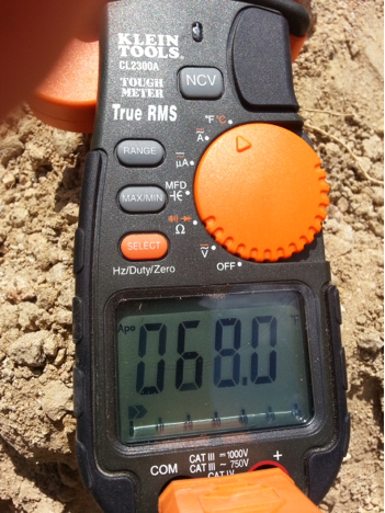
Outlet temperature in Fahrenheit from one of the cooling tubes measured on a 90.5 degree day in late summer. Photo by R. Freudenberger
A legitimate concern with any earth tube installation is the accumulation of condensation in humid climates. For the fly larvae, this is not an issue since their environment is already fairly humid with food scraps and moist residues. In the event that moisture builds up in the floor of the tubes, which has not occurred so far, we’ve included standpipes at the lowest end of the runs so we can pull any water buildup out from the surface with a small suction pump.
Earth-tempering principles also apply in the winter. When outdoor temperatures are far below what’s needed to keep the insects active, the relatively warmer air from the tubes tempers the inside environment. More significantly, the container was placed alongside our biochar facility which generates a substantial amount of hot water in process. Our biochar crew installed a radiant floor heat system in the concrete floor we poured over the subfloor of the container, so the soldier fly facility can readily tap off the hydronics for heat any time it’s needed.
The earth-coupled tubes are only part of the bigger picture of soldier fly production, and as we develop and improve our propagation system we’ll host workshops to share what we’ve learned about breeding and using the black soldier fly, and applying resilient technologies to that purpose.