Last weekend I had the privilege of leading Living Web’s first workshop for 2018. Tech workshops tend to work best in the winter, before the growing season kicks in. Cold weather and a stiff wind kept us in the classroom and bundled up tight for a brief tour of some of the low voltage control systems around the Grandview Biochar Facility.
Leading a six hour workshop means you can take your time and cover the fundamentals before honing in on the specifics. Still, understanding how to use low voltage controls to help run your small farm more efficiently is no small task. I thought the blog format would be useful as a way to cover some of the highlights from last Saturday while providing links for further study. I’ll start out today on a brief soapbox before coming down to introduce some basic control circuit vocabulary. Next month I’ll pick it back up and finish by mapping out some control circuits that include some readymade controllers to do some simple, but necessary work.
Appropriate, and Inappropriate Technology
Last weekend’s controls workshop was about introducing the vocabulary of some of the behind the scenes processes that keep us comfortable, safe and efficient. First off, we’re not in a position to advise building these systems from scratch. It’s important to know your limits, and recognize when you put you people and property at risk. That said, I’m a firm believer that, as owners of these appliances and machines that play such an integral role in our lives, it’s at least in some part our responsibility to understand, and have the ability to troubleshoot and perform basic repairs when the need arises.
When we talk about controls, it’s important to recognize the difference between those that remove the human element – rendering us lazy and unaware – and those that we can work alongside, gathering useful data and substituting human effort for only the most mundane and inefficient tasks. Take for example the case of irrigation controllers: today’s newer models have ‘improved’ upon older ones by including wi-fi connectivity to access weather forecasts and control irrigation solenoids accordingly. Contrast this to the RainBird SMRT-Y soil moisture sensor kit that saves water by interrupting an irrigation schedule when the soil is already moist, and works alongside any 24 volt irrigation timer, whether the internet is down or not. Ask yourself, do you really need to control your sprinkler with a cell phone? We’re all familiar with the narrative of our tendency to overplay high tech systems that can leave us exposed when these systems fail. Of course I understood the useful applications of these systems, but there’s a time and a place: when user-repairable components are replaced with non-repairable parts in the name of technical progress, something is lost.

The Farmbot Genesis Open-Source CNC Raised Bed. Clocking in at $2495 this machine is essentially a watering system that allows you to plant your garden as a videogame, pushes weeds underground (no mulch?) and sends text message alerts when your crops are ready for harvest.
I’m only part Luddite: no doubt, the Farmbot is an amazing work of open source tech that will serve well as an educational tool, and to some become a gateway to sensible agriculture. And there are inherent advantages with IOT when applied to small agriculture, as long as we maintain a means for human intervention. The SwitchBox control is a complete kit for controlling standard 120V outlets with your cell phone. And, for those more initiated, there are many online tutorials for DIY versions of SMS controlled outlets at a much lower cost. I’m sure there are many of us that would like one of these to open the chicken coop door, or start the block heater on the tractor on a frosty morning. Earlier this summer in our greenhouses, we used a combination of two Android apps that make use of older, otherwise irrelevant phones: Tasker for automatically controlling a phone camera for overnight data collection in some germination trials, and Alfred which allows you to use your phone as a remotely monitored security camera. With a motion activated alert feature, certainly someone could use this to catch a chicken thief in the act.
Low Voltage Controls
High tech aside, let’s get back to basics. A simple electrical control system really only involves three things: a power source, a switch and a load. A common light switch will allow power from the utility to energize a lightbulb. Low voltage controls, however, are inherently safer, more cost efficient, in some ways more capable and easier to install. First, we’ll take a look at some basic components of a low voltage control system: transformers, switches and relays, and see a few simple control circuits we built for the greenhouse and our tracking solar array.
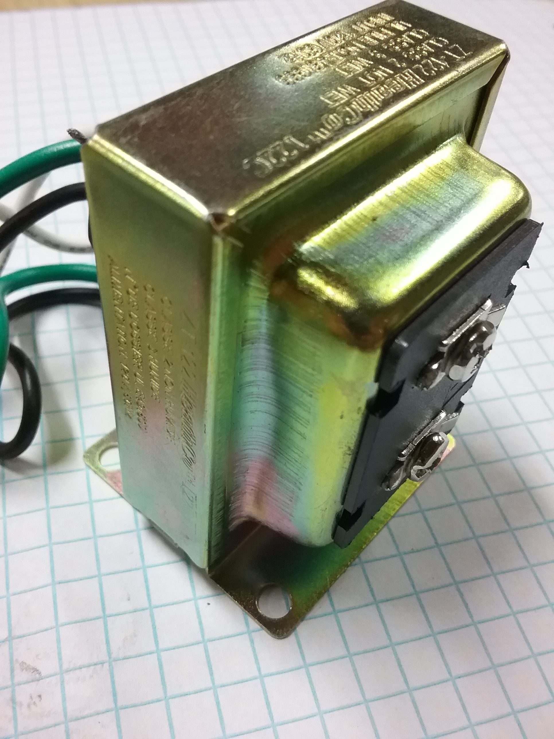
A small doorbell transformer like this takes 120Vac down to 24Vac and typically provides enough power for relays, thermostats and more in our control circuits.
Transformers are devices that either raise or lower an incoming primary AC voltage to a usable secondary voltage. Depending on the application, transformers can ‘step up’ the incoming voltage (microwaves, arc welders) or ‘step-down’ transformers such as those on the telephone pole in your neighborhood. We’re most interested in the 24V control transformer. You can find these everywhere, chances are you’ve already got at least one for your doorbell or inside your furnace. For most applications around the Grandview Facility we’re using pri:120V, sec:24V transformers rated at least for 40VA. VA is very similar to Watts: a measure of the amount of power a transformer will provide.
Switches come in an immense variety of styles and functions. Since there’s no way I could even come close to covering it all, I’ll mention a few interesting ones we’re using in our control circuits. But first, we need to understand a few basic terms.
[tribulant_slideshow gallery_id=”2″]
Admittedly this is a little dry, so let me try to inspire showing a popular example of a way we can use switches to make our lives easier: the three-way lighting switch. Chances are you have this circuit in your home, where you can toggle an overhead light on or off from either of two switches located on opposite ends of the room. If you were to pull off the switch cover plate and observe it’s likely any novice would be overwhelmed by a indiscernible mess of wires. However, when expressed on a line diagram it’s easy to see that a three-way lighting circuit is nothing more than two SPDT switches wired in series.

The light is energized when both SPDT switches are in the up or down position. Move either switch and the circuit is broken.
So far we’ve only covered small, manually operated switches. A crucial step towards understanding low voltage control systems involves knowing how relays work. Think of Relays as electrically powered switches, that are often employed by control circuits to energize larger loads, or otherwise isolate circuits. Just like switches, relays can look quite a bit different from one another – each with its own application. The starter motor solenoid in your car is a type of relay. Turn the key, and control power from your car’s ignition switch energizes a coil, that closes a circuit from your battery to the starter motor. If your car didn’t have this relay, your ignition switch would have to be rated for the full load current of the starter motor: as much as 250Amps or more! What we’re going to focus on are 24V electromagnetic ‘ice cube’ relays that close a switch between common and ‘normally open’ when 24 volts is applied to ‘the coil’. Scroll through the photos below to learn a bit more about relays.
[tribulant_slideshow gallery_id=”3″]
When you begin to imagine the applications for relays, first you’ll realize that relays are everywhere, and then you may see that relays can make a lot things possible that you might not have otherwise thought of. For example, our greenhouses are the constant inflation type: requiring a small blower to maintain air between two layers of plastic film. They’re great for insulating air pocket it creates and can keep a tight greenhouse much warmer in the winter than single layer poly versions. However when the grid goes down, we’d otherwise lose inflation and our greenhouse walls would be a floppy mess if we didn’t have a relay activated, battery powered DC backup blower. This circuit is simple: A 120Vac relay stays energized as long as the grid is present. The DC blower is connected to the battery by way of the N/C contact the relay. So, as long as the grid is present, the relay is energized and makes common to N/O, and the DC fan won’t turn on. It’s not until we lose power that the relay reverts back and makes common to N/C, completing the DC blower circuit.
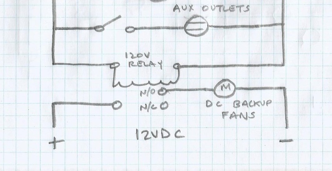
DC backup with a 120Vac ‘grid sensing’ relay
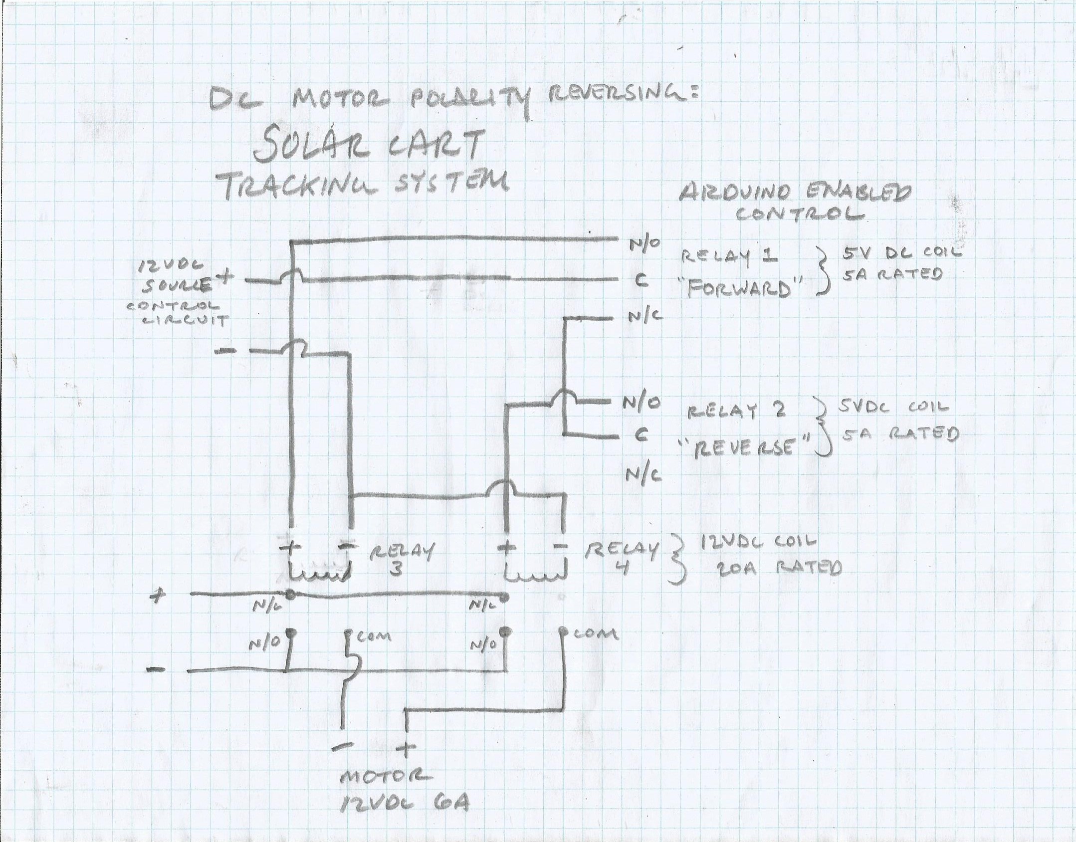
Next time I’ll cover some of the ‘ready made’ controllers we use, along with relays and switches, to do fun things around here, like energizing a stoplight and buzzer when our biochar retorts get too hot, or, for optimizing our solar kiln operation. I’ll wrap up today with one more example of how we use relays: the motor reversing circuit on our our 400W tracking solar trailer. In this case, we’re using an Arduino microcontroller to advance our simple tracker westward 15 degrees every hour. The arduino board sends out a 5v signal to a relay that’s only rated for switching 5 amps max. We had to then step up to another relay capable of handling the full load of the tracker motor. At the end of the day, the tracker motor reverses by switching polarity and reverting back to it’s original, pointing eastward, morning position. We programmed the arduino board to do this automatically, but we’re not pros, so we used relays to make sure that the motor couldn’t receive a command to move forward and reverse at the same time. If the arduino fails to recognize the end of day, repurposed N/C lawnmower safety switches are wired in series and used as limit switches, so the tracker won’t tear itself apart. See the circuit diagram and you’ll see how a couple of relays both protect the motor and switch motor polarity upon receiving the signal.